How to Read Oil and Gas P&ID Symbols Kimray
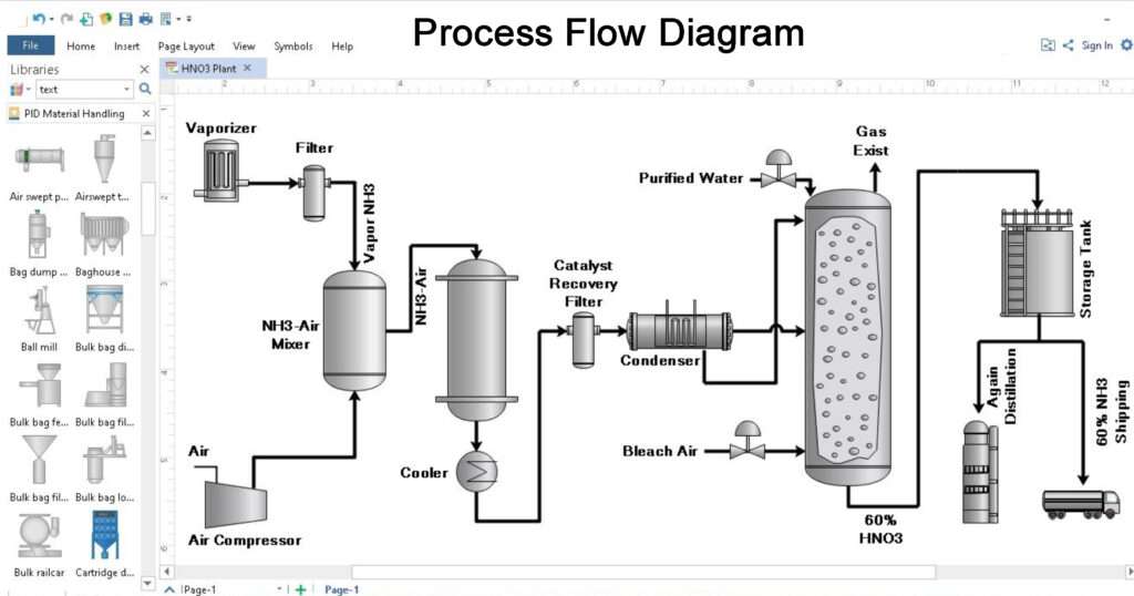
A Process Flow Diagram (PFD) is a simplified diagram that shows the process flow of a manufacturing process in proper sequence. This diagram should consist of every essential detail like main equipment, Heat, Material, & Energy Balance, tag number, chemical composition, etc.
Learn P&ID Diagram Basics Symbols To Read P&ID Diagrams Easily
Process Flow Diagram Symbols The vector stencils library "Inductors" contains 41 symbols of inductor elements for drawing electronic circuit diagrams. "An inductor, also called a coil or reactor, is a passive two-terminal electrical component which resists changes in electric current passing through it.
What Is Process Flow Diagram Pfd How To Examples Edrawmax Riset
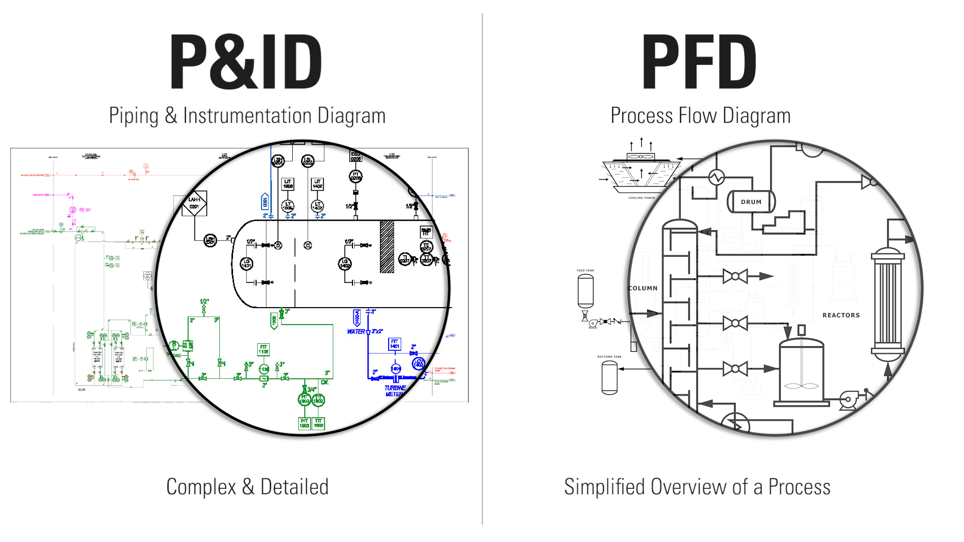
A process flow diagram provides a quick overview of the entire operating unit or a system. A technician or engineer can use this document to trace the flow of materials through the unit. The flow diagram is also used for visitor information and new employee training. It is one of the core documents for drawing the Plot Plant and P&ID.

Process Flow Diagram (PFD) A Complete Guide
A process flow diagram (PFD) is a diagram used in chemical and process engineering to indicate the general flow of plant processes and equipment.

How to Read Oil and Gas P&ID Symbols Kimray
A block flow diagram (BFD) is a drawing of a chemical processes used to simplify and understand the basic structure of a system. A BFD is the simplest form of the flow diagrams used in industry. Blocks in a BFD can represent anything from a single piece of equipment to an entire plant. For a complex process, block flow diagrams can be used to.
Process Fundamentals — Introduction to Chemical and Biological Engineering
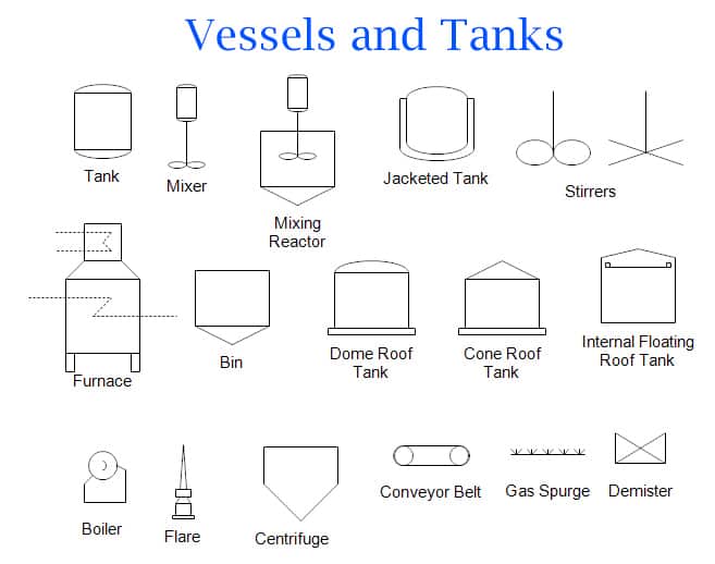
A process flow diagram (PFD) is a type of flowchart that represents the integrity of equipment and plant operations. This graphic chart depicts a link among the principal equipment of a facility.. Types of Engineering Symbols in PFDs. The symbol shapes must be consistent. Centrifuges: Centrifuges are instruments that isolate mixture elements.
181 Process Flow Diagram (PFD) Symbols for Engineers Vista Projects
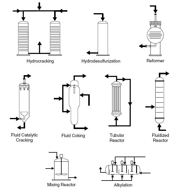
PFDs: Reactor Symbols LearnChemE 168K subscribers 6.3K views 9 years ago Process Design Organized by textbook: https://learncheme.com/ Describes the reactor symbols used on a process flow.
Difference between PFD and P&ID with Example Inst Tools
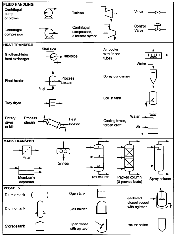
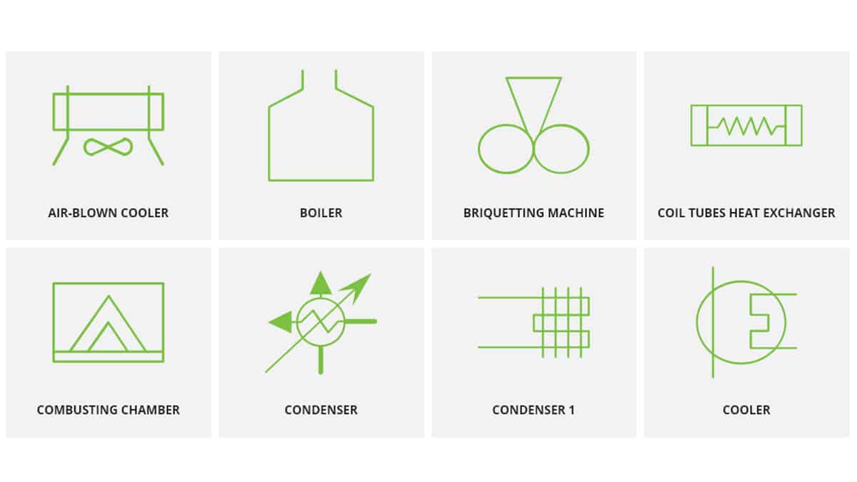
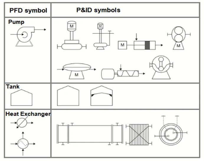
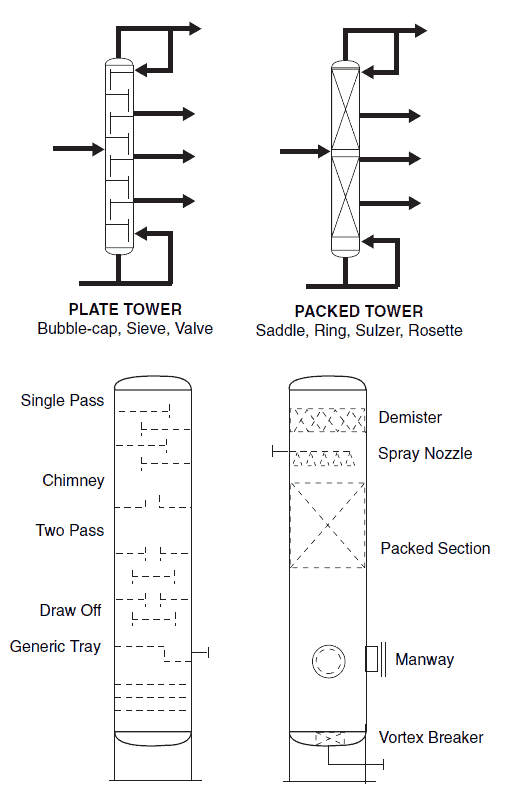
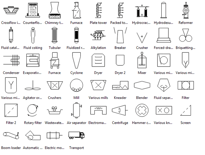
Having understood the importance of a process flow diagram(PFD) from: What is a Process Flow Diagram (PFD)?:The Basics, here is a comprehensive list of the common symbols of process equipment used in preparing PFDs and P&IDs.I have dealt with some of these symbols listed here before in Common P&ID Symbols Used in Developing Instrumentation Diagrams but here again is a comprehensive list of.
Common Process Equipment Symbols Used in Developing Process Flow
Process flow diagrams PFDs show how industrial process equipment is interconnected by a system of pipelines. A PFD is more conceptual than a P&ID, and usually includes more annotations that display data. Create a piping and instrumentation diagram In Visio, open any of the following templates: Piping and Instrumentation Diagram Process Flow Diagram

Process Flow Diagram (PFD) of the highpressure reactor unit. (1
The PFD shows the sequence of flow through a system through the various equipment (such as piping, instrumentation, and equipment design) and details the stream connections, stream flow rates and compositions and operating conditions through the plant layout.
P & ID y PFD Drawing Symbols and Legend list (PFS & PEFS) Chad Wilken's
Other items of interest. A PFD can be computer generated from process simulators, CAD packages, or flow chart software using a library of chemical engineering symbols.Rules and symbols are also available from standardization organizations such as: ISO 10628: Flow Diagrams For Process Plants - General Rules; ANSI Y32.11: Graphical Symbols For Process Flow Diagrams (out of print but in stock as.
Process Flow Diagram Software for Linux Edraw
The process flow diagram (PFD) represents a quantum step up from the BFD in terms of the amount of information that it contains. The PFD contains the bulk of the chemical engineering data necessary for the design of a chemical process. For all of the diagrams discussed in this chapter, there are no universally accepted standards.
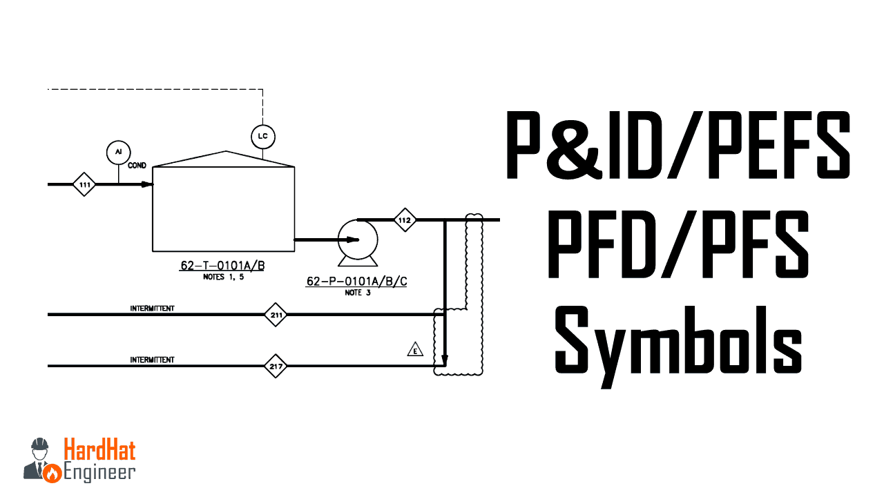
P&ID and PFD Drawing Symbols and Legend list (PFS & PEFS)
You can download this presentation for free. The link is available in the description. PFD and P&ID are also known as PFS and PEFS. PFD is a Process Flow Diagram. P&ID is a Process or piping & Instrument Diagram. PFS means Process Flow Scheme, and PEFS means Process Engineering Flow Scheme.
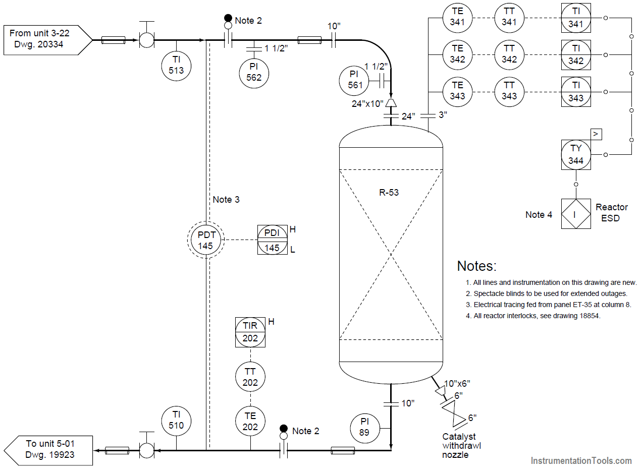
Questions on Chemical Reactor Vessel P & ID InstrumentationTools
Reaction kinetics & Reactor Reference books (1:18). Plug Flow Reactor (PFR) (4:23) Packed Bed Reactor (PBR) (4:15) Reactors - P&ID Symbols (2:03) Process Diagrams Introduction to PFD & P&ID (0:36) What is a PFD? (3:08) Process Flow Diagram - Exercise 1 (6:53) Process Flow Diagram - Exercise 2 (2:38) Process Flow Diagram - Exercise 3 (7:36) P.

Basic PFD Symbols in 2022 Process flow diagram, Process flow, Basic
Mixers Symbols. There are a number of other standard symbols included in PFD diagrams with a multitude of functions, as shown below. ANCHOR AGITATOR. CROSS-BEAM AGITATOR. DISC AGITATOR. GAT PADDLE AGITATOR. HELICAL AGITATOR. IMPELLER AGITATOR. IN-LINE MIXER.

Process Tech & Oper Acad Determining HEx Service
Once a process flow diagram is made, P&IDs help engineers develop control strategies that ensure production targets are met while meeting all safety and environmental standards.. Also, symbols used in the P&ID are uniform throughout. Diagrams for heat exchangers, continuously stirred tank reactors (CSTRs), and distillation columns shown in.